Assembly Guide
Table of Contents
No sections found.
0. Introduction
Recommended printing paper and assembly methods vary depending on the model you are assembling.
First, check the model-specific information in “0-1. Quick Guide.” Once you are familiar with the basics, you can proceed using only this guide.
If you need more detailed explanations of each process or basic knowledge common to all models (how to use tools, meaning of symbols, etc.), refer to Chapter 1. For tips and techniques to achieve a clean finish, refer to Chapter 2.
0-1. Quick Guide
You can quickly find the optimal assembly process for each model.
Enter the model name in the search bar below to check what you need and the steps.
Select a paper model to assemble
1. Assembly Essentials
This chapter explains the detailed rules for each process and the basic knowledge common to all models.
1-1. Preparation of Templates, Assembly Method, and Paper (Ex: Oil Drums)
In this step, check the following four items before starting assembly.
1) View Individual Page: Open the “Individual Page for Oil Drums” below.
2) Confirm Files: Before downloading, check the ☑ marks for “Template” and “Assembly Method” in the “Model Data” section of the preview screen. This allows you to confirm which files are available for that model. [1_Template], etc. represent [ID_Filename]. For details, see “About Each File” below.
3) Download: Download the required files using the “Black Button” at the top right of the preview screen.
4) Check Printing Paper: Confirm the recommended “Printing Paper” listed in the model data. *The recommended printing paper listed here is primarily products available in Japan. While I can suggest Japanese printing paper, I do not have sufficient knowledge of equivalent paper available overseas. Therefore, please refer to the “Product Data” on each linked page and use it as a reference when searching for similar printing paper in your region.
Template [1_Template]: Required file. Be sure to download it.
Template Guide & Manual [2_GuideManual]: The latest guide for assembling the template. Obtain it together with 1_Template.
Assembly Instructions [3_Instructions]: Legacy instructions (optional). These may not be included depending on the model, but you can still assemble the model using “2_GuideManual.”
1-2. Materials and Tools
This section introduces the materials and tools required for assembly. They can also be viewed on the Supplies page.
Materials: Optimal printing paper varies by each model. It is recommended to use the paper specified in Item 4) of Step 1-1, or to select a similar type of paper.
Tools: Check ”✓ Required Tools” and ”+ Optional Tools” below. Items marked with ”+” are not required, but they make the process easier and help improve the final result.
Inkjet Printer: Used to print the template PDF. Prepare a home printer or use a service that supports printing with your own paper.
Quick-drying Wood Glue: A fast-drying wood adhesive.
Metal Spatula: Or a toothpick. Used for applying adhesive. Take a small amount of glue into a separate container, then pick it up with the spatula and apply it to the bonding area. Useful for precise application in small areas.
Plastic Container: A hinged-lid container or a yogurt cup covered with plastic wrap to prevent drying. Used to dispense a small amount of glue as needed.
Cutter Knife / Scissors: Used to cut out the templates. Since there are many small parts, a cutter knife is used more frequently.
Cutting Mat: An A3 size or larger mat is recommended, as it provides more working space than A4 size.
Ballpoint Awl: Or an empty ballpoint pen. Used for scoring, as described in Item 1) of Step 2-1.
Ruler: Used together with the ballpoint awl or cutter knife.
Ball Tool: Used to press and reinforce seams. The actual usage is explained in Item 6) of Step 2-1.
Tweezers: Used when attaching small parts.
Lacquer Thinner and Cotton Swab: Used to make glue stains less noticeable.
Color Markers / Colored Pencils: Used to color the white edges of the cut paper.
Cylindrical Object: Such as tubes, pipes, or rods. Used for shaping curved parts of the template.
Clear Varnish Spray / Multi-purpose Water-based Spray (Clear) / Pastel Fixative: Used depending on the paper type for long-term preservation and surface gloss adjustment.
1-3. Printing Preferences
This step introduces the printing preferences for the template PDF data.
For detailed explanations, please view the PDF preview below or download it.
The first page explains single-sided printing, and the second page explains double-sided printing.
1-4. Symbols and Terms Used
This step introduces the symbols and terms used when assembling the models.
The “List of Symbols and Terms” below summarizes the template symbols on the left and their specific meanings on the right.
Note that this list is a comprehensive overview; only the symbols actually used will appear on your template.
Some symbols not listed here may be used for specific paper models.

(Solid Line)
Cut Line

(Dotted Line)
Mountain Fold

(One-dot Chain Line)
Valley Fold

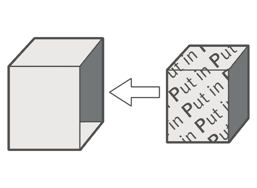
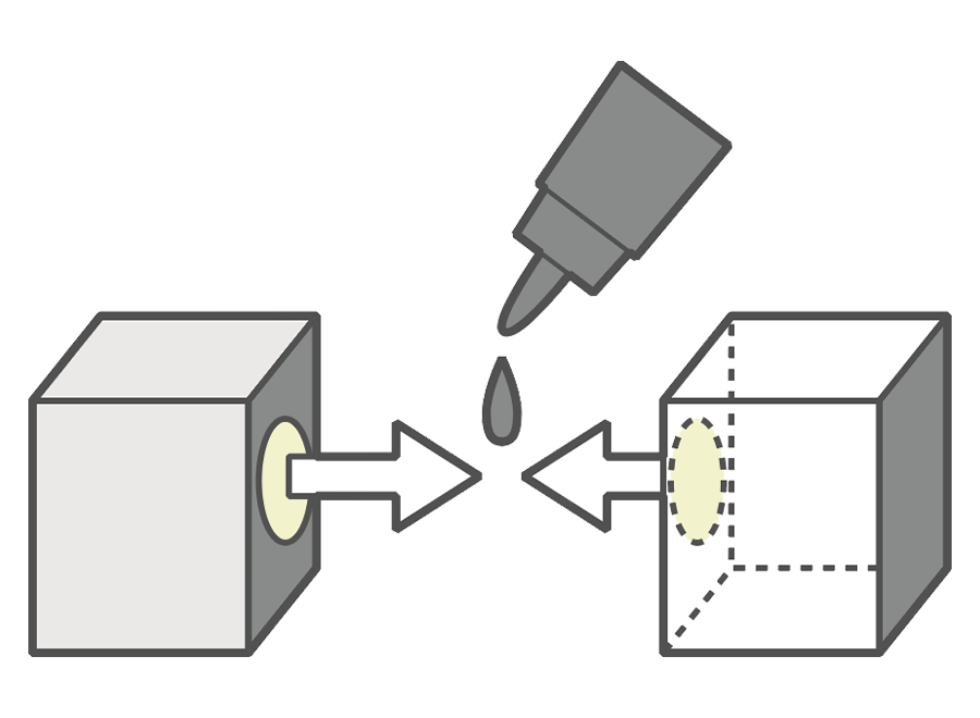
(Pattern 1)
Glue Spot

(Pattern 2)
Fold Tab
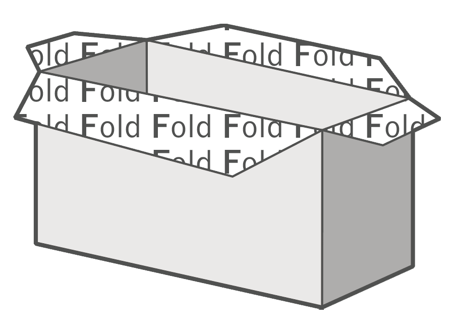
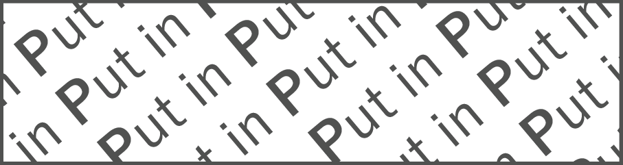
(Pattern 3)
Put In

Cut-Out Mark


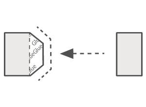
Glue Mark

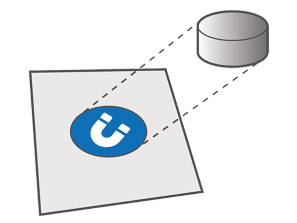
Magnet Mark

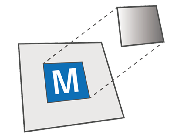
Metal Plate Mark

Guide
1-5. Choosing the Assembly Method
I am currently transitioning to “Template Guide & Manual [2_GuideManual]” for a more intuitive assembly experience. For details, please check 1. Notice (2026.04.16).
Depending on when the model was released, the assembly method will fall into one of the following three patterns. Proceed according to the ☑ mark for the assembly method you confirmed in Item 2) of Step 1-1.
This template is a dedicated guide for visually confirming correct glue positions and symbols. By using it alongside the included “Manual,” you can complete the model with the following features:
Connection Numbers: You can intuitively confirm the assembly order by following the rule of “matching the same numbers” on the template.
Symbol Confirmation: The surface design is semi-transparent, clearly highlighting symbols (such as fold lines) that tend to be hidden by the artwork.
Check the actual Template Guide & Manual using the Oil Drums sample below.
These are individual, diagram-based instructions included with older models.
Recommended Approach: Even for older models, a more intuitive “2_GuideManual” may be available. I recommend checking for its availability first and prioritizing its use.
Using the Old Format: You can also proceed using the conventional “Assembly Instructions.” Use this format if you prefer to confirm each step through detailed illustrations.
Check the actual Assembly Instructions using the Oil Drums sample below.
The “Basic Assembly Guide” method involves assembling the model using hints provided directly on the template, such as arrows (indicating where to glue tabs), “glue marks,” and brief explanatory text. This method is used when no dedicated manual or instructions are provided.
The arrows refer to the symbols at the bottom of the “List of Symbols and Terms” in Step 1-4. The “glue marks” refer to the fourth symbol from the bottom in that same list.
2. Assembly Support (Ex: Oil Drums)
This chapter uses the Oil Drums model as an example to introduce assembly tips, Sketchfab usage, and video support to help you assemble better.
2-1. Assembly Tips
This step introduces techniques for assembling models successfully. Following these steps will help you achieve a beautiful finish.
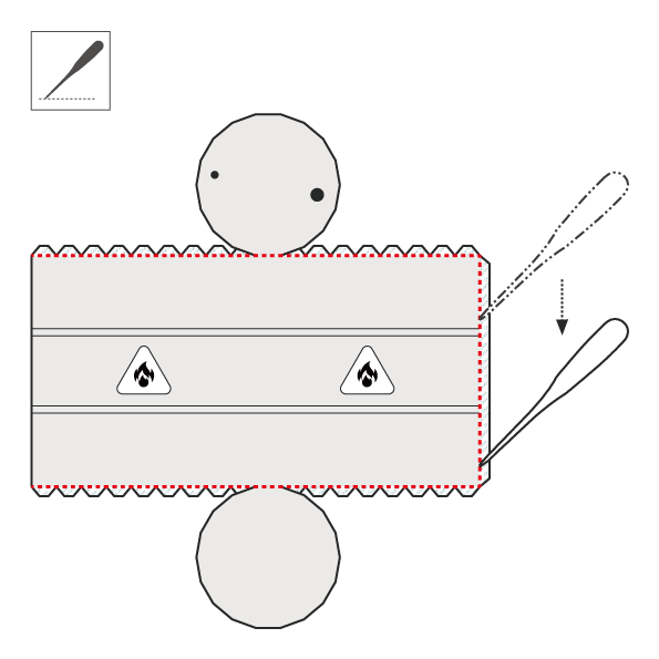
1) Scoring: Score the fold lines using a ballpoint awl and a ruler referring to the figure below.
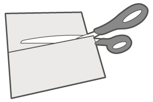
2) Cutting: Cut out the template according to the “Cut Line” in Step 1-4.
3) Painting: Color the cut edges of the template with markers or colored pencils.
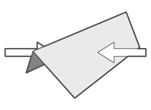
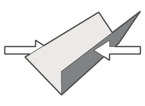
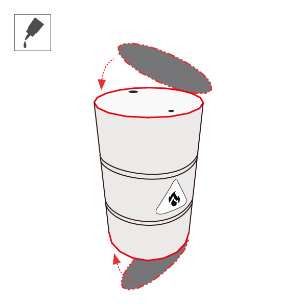
4) Folding and Bending: Refer to the figure below, fold the tabs at glue spots, and bend the surfaces using a cylindrical object.
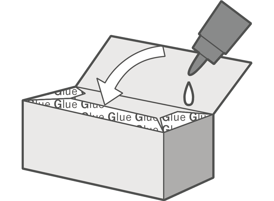
5) Gluing ①: Glue according to the “Glue Spot” and “Guide” in Step 1-4, or the assembly diagrams.
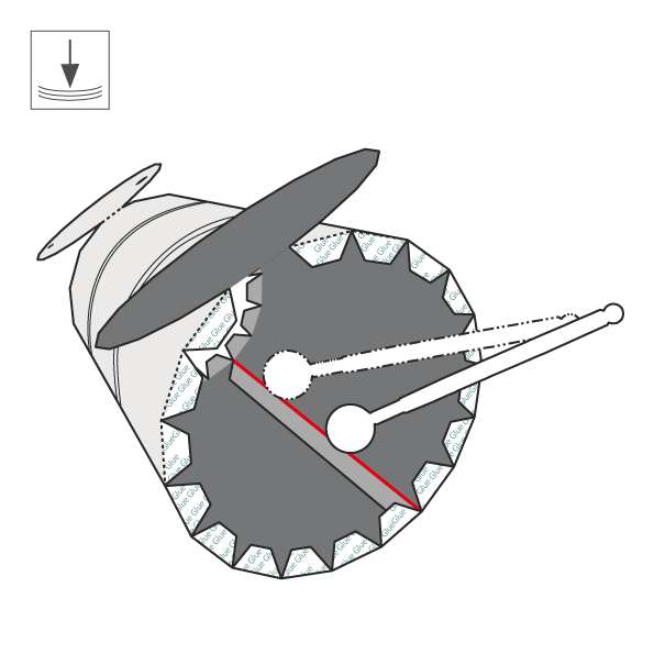
6) Pressing: Press the red lines shown below from the back with a ball tool. This makes the seam lines less noticeable.
7) Gluing ②: Same as step 5).
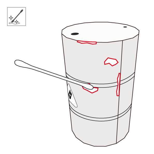
8) Removing: If glue stains occur, they can be made less noticeable with “lacquer thinner and a cotton swab.”
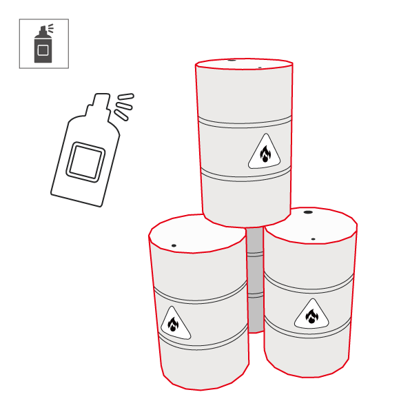
9) Spraying: Spray if you want to change glossiness or preserve the model for a long time.
1) Scoring
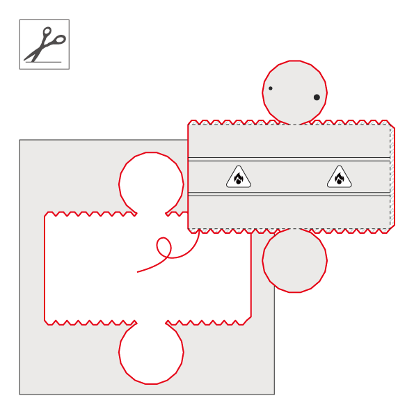
2) Cutting
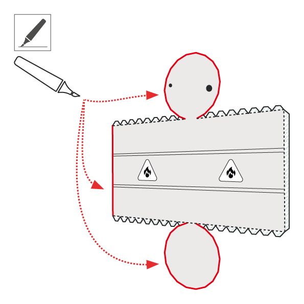
3) Painting
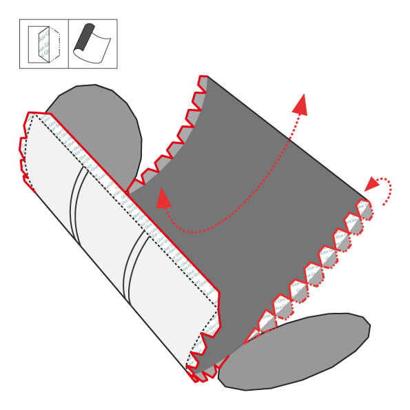
4) Folding and Bending
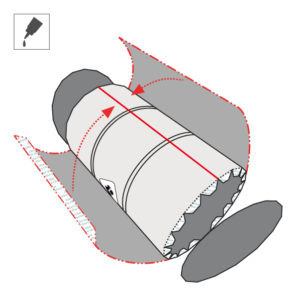
5) Gluing ①
6) Pressing
7) Gluing ②
8) Removing
9) Spraying
2-2. 3D Model Viewer (Sketchfab / P3d.in)
This section explains how to use 3D viewers to display models. By using these tools, you can gain useful insights for assembly from the following two aspects:
360° Shape Viewing: You can rotate the 3D model freely and view it from all angles.
Display Mode Switching: You can switch between the model’s surface design and wireframe view.
Access
There are several ways to access the model. Please choose one of the following options:
- External List: Browse and open the desired model from Sketchfab Models.
- Individual Page: Open the viewer from each Paper Model page.
- Quick Guide: You can directly access the embedded viewer in the guide.
Basic Viewer Controls
- Rotate: Left-click and drag to rotate the view.
- Zoom: Use the mouse wheel to zoom in and out.
- Pan: Middle-click and drag to move the camera.
How to Switch Display Modes
1) Open Inspector: Click the “Model Inspector (i)” icon at the bottom-right of the model page.
2) Wireframe Mode: Select “Wireframe” from the “GEOMETRY (3)” menu on the left.
3) Return to Normal View: Select “Final Render” from the “RENDER (1)” menu.
Below is an example of the 3D model viewer.
Access
There are several ways to access the model. P3d.in models are set to private, so they cannot be accessed via external lists.
- Individual Page: Open the viewer from each Paper Model page.
- Quick Guide: You can directly access the embedded viewer in the guide.
Basic Viewer Controls
- Rotate: Left-click and drag to rotate the view.
- Zoom: Use the mouse wheel to zoom in and out.
- Pan: Right-click and drag to move the camera.
How to Switch Display Modes
1) Open Menu: Click the “Viewport display style” icon on the left-side black toolbar.
2) Toggle View: Select “Wireframe” or other display modes to inspect the model structure.
Below is an example of the 3D model viewer.
2-3. Assembly Video (Under Preparation)
This step explains assembly support via video. By watching the sequence of assembly in the video, you can intuitively understand finger movements, timing for glue, and precise angles—providing essential assembly hints that are hard to grasp from 2D diagrams alone.
3. Others
This chapter explains cautions and supplementary information for assembly.
3-1. Cautions
This section explains safety precautions and basic specifications.
Handling Sharp Tools: Use sharp tools carefully and always work on a cutting mat. This site is not responsible for injuries.
Ventilation and Protection: Ensure proper ventilation and wear a mask when using adhesives or sprays.
Bleed Painting: Templates include bleed areas to reduce visible white edges.
English Notation: English is included for international users. Please report any errors.
Paper Characteristics: Some paper types may discolor under sunlight.
Storage: Avoid direct sunlight and high humidity to prevent warping and discoloration.